
muBox: a Hackable Electronic Music Box

Code + Schematics available on Github
This lovely group of lights is actually diffused LEDs from the muBox. The muBox (pronounced “mew-box”) is my attempt at creating a hackable, electronic music box. I have been using the Sparkfun Music Instrument Shield and the pic18F often recently, so I decided that instead of using breadboard and jumper wires all the time, I would populate the microcontroller and the shield onto one board. During the design, I realized that the setup could be more than just a prototyping convenience. Thus, the muBox was born!

muBox Overview
Here’s an overview:
Here is a simple sequencer program running on the muBox:
Here is the muBox running a program which uses the Collatz Conjecture to determine notes
Physical Design [Microcontroller] The microcontroller (uC) is an AtMEGA 328p which handles the user input and MIDI communication. I originally wanted to use the PIC uC but I decided that if anybody else was interested in making a muBox of their own, an Arduino based environment would probably be more convenient. The uC takes input from a potentiometer (via analogRead()) and two momentary switches which are attached to pins with external interrupts, so anybody programming the uC could attach interrupts if they wished.
[Sound Generation] All sound generation is handled by the VLSI VS1053 chip. This chip contains a large bank of sounds (instruments and percussion) and plays them back upon reception of MIDI commands from the microcontroller. The VS1053 is also an MP3 decoder (it actually decodes other formats as well), but only the MIDI functionality is used for the muBox…so far.
[LED Driver] I wanted to add some kind of indication system as well as add some kind of aesthetics onto the muBox so I decided to add some differently coloured LEDs arranged in a circle (because let’s face it, if the LEDs were in a row, that would be boring!). Sixteen LEDs are driven by TI’s TLC5925 LED driver. The microcontroller sends a 16-bit string via SPI and the driver lights the LEDs accordingly.
[Amplifier] To amplify the sounds generated by the VS1053 chip, I’ve placed a simple amplifier circuit using the LM386 op-amp. Powered by 5 V, the voltage swing is from -2.5 V to +2.5 V which should be pretty audible. I originally decided to attach an 8Ω speaker underneath the board, but difficulties in debugging forced me to attach a 3.5mm audio jack instead. Out of all the individual parts, this would benefit from the most work.
[Power] Finally, what would the entire board be without power? Since there are three different voltages at work here (5, 3.3 and 1.8 V), there are three regulators. The 5 and 1.8 V use the Micrel 5205 and 5265 respectively. For 3.3 V, I wanted to use a regulator that could handle more current output since the LEDs were fed 3.3 V so I used the CAT6219 regulator by ON Semiconductor which was able to output up to 500 mA of current. The entire board is powered by a 9V battery.
Software Design
Because the muBox can be programmed to do different things, software is open-ended. The only real permanent portion of software are the MIDI functions for communication to the VS1053 but even that can be changed by anybody to suit their needs. The MIDI functions are based off of Nathan Seidle’s and Rick Winscot’s code for the Sparkfun Music Instrument Shield. Thanks guys!
The two programs written so far for the muBox are Sequencer and Collatz.
[Sequencer] As its name suggests, the sequencer program is a sequencer much like the ones you see on just about every commercial controllers out there in the world (Monome, Ableton…). The program will repeat a certain musical sequence defined by the user continuously until interrupted. On startup, the user defines how many notes will be in a sequence by adjusting the potentiometer. The number of notes is indicated by which LED lights up. If the third LED lights up, then there will be three notes. The user can define up to a maximum of 16 notes. The number is selected by pressing a button, then the program will move to the next step.
The next step is where the user defines the notes he/she wishes to play. Again, using the potentiometer, each LED plays a different note. The note is selected by pressing a button. This continues until the number of notes defined by the previous selection mode is reached. The bank of selectable notes can be changed by modifying the code directly. Once the last note is defined, the program will play the notes continuously.
[Collatz]
This program requires you to be familiar with the Collatz Conjecture. If you don’t know what it is, let this XKCD comic explain:
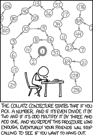
In short, if you take any number and apply the above rules, you will always end up at 1 (this has yet to be formerly proven). For more information, check out the Wikipedia link. I decided to have some fun with this mathematic problem and incorporate it into the muBox.
On startup, the user defines a number from 0 to 1023. Once a number is chosen, the user can hit the start button to start the mathematical sequence. The program steps through each calculation. If the result of one calculation is an even number, then a tone from a predefined scale (notes in an array) will play. If the result is odd, the program will change the chord progression and the subsequent even numbers will follow the scale in the new chord progression. This continues until “1” is reached, at which the program terminates and the user can try another number.
The user can also change the instrument (piano, harp, vocals etc…). The bank of instruments can be hard-coded in software.
Construction
The PCB was designed in Eagle and fabricated by Alberta Printed Circuits. Surface mount components were mostly used to save some costs and to practice my SMD soldering skills. The board is supported by four 4-40 screw compatible, 1″ nylon standoffs. I hope to have an acrylic case made soon.

APC does a great job making PCBs

well…that’s embarassing

aaaaarrrrrgggghhhhh!!!!!!!!!!!
Debugging
EVERYBODY loves this step! I’ve had some problems burning the Arduino bootloader onto the uC. I didn’t have a ISP programmer handy so I decided to use the Arduino UNO and the Arduino IDE to burn the bootloader. For some reason, they did NOT want to play nice! I kept getting programmer errors using the IDE so I decided to find the hex file and use AVRDude instead of the IDE to burn the bootloader and write my program. Thankfully, that worked…kind of. While the chip was programmable with the ISP programmer, it was not programmable using the FTDI board typically used to program the Lilypad and Arduino Pro Mini. I’ll have to investigate this further.
Once I soldered all the components on and flashed the uC, I turned on the board and of course, nothing happens. The LEDs were lighting up fine and MIDI commands were being sent to the VS1053, but no sound was coming out! I had tested the amplifier before I soldered on the VS1053 and I found no problems. On closer look at my soldering job, I found out that not all the pins had been soldered on properly. D’oh!

The pins in the red box don’t seem like they were properly soldered
I added some more solder onto the VS1053 and hoped for the best, but still no sound!! The VS1053 was not outputting anything to the amplifier. I fought with this for hours, placing logic analyzer and oscilloscope probes everywhere. Originally, I attached the speaker directly to the amplifier output and I thought this might be the problem so I replaced the speaker with a 3.5mm audio jack and plugged it to another amplifier. I turned on the board and got a lot of noise, but I could barely make out some tones. Excited, I adjusted the gain on the board and…voilà! We have sound!! This was where I punched my fist into the air and jumped with glee (seriously…when you’ve been debugging in frustration for hours, you have a free pass to look like an idiot)
I’m still 100% sure on why I haven’t been able to get sound but I have some possible theories. First, I may have applied too much heat to the trimpot that adjusts gain on amplifier and it may have been ruined. The trimpot is extremely sensitive. Turn even a tiny bit and you will lose sound. Second, the data sheet on the VS1053 specifies that a pin, “GBUF” should have been connected to the -ve lead of the speaker or audio jack. I suspect this might have something to do with my woes.
Ending Notes
If you’ve read this far…wow good job!
I would like to make some revisions to this board. Here’s a list:
- Enable uC programming with FTDI headers and not just exclusively the ICSP header
- Fix the sound issue and make the muBox standalone by adding a speaker to it
- Break out unused pins on the uC
- Use Schmitt Triggers for interrupt pins to minimize debounce
- Design a nice case for the muBox and maybe even diffuse the LEDs
- Write a proper library to make programming easier
I may end up making a kit out of this someday. If I ever do, I would like to source another chip for the MIDI functions. The VS1053 sells for about $20. That is one expensive chip! I would also like to redesign the PCB using through-hole components, making the kit a bit easier to solder. For now though, having a working muBox is enough to crack open a can of beer and celebrate!
Acknowledgements
Collatz Conjecture Comic from XKCD: http://xkcd.com/710/