Take a look at these two waveforms pulled from a UART line with a logic analyzer. Notice anything interesting?


If you do have this figured out, then congratulations! You were able to solve this puzzle two weeks faster than I have.
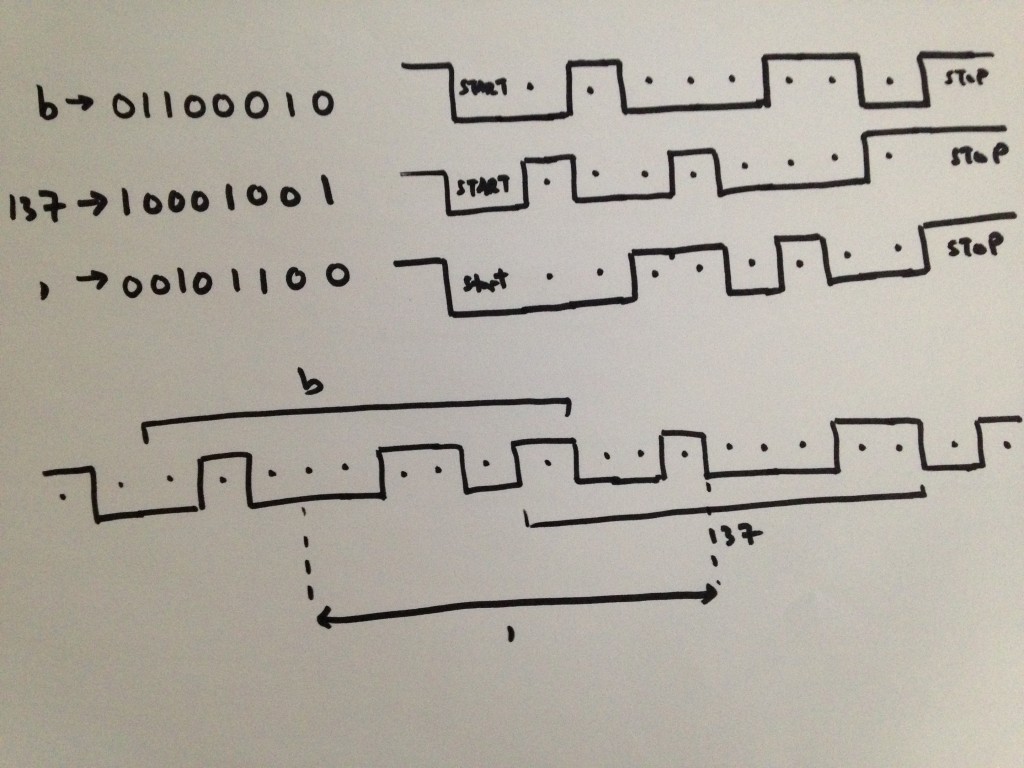
The two waveforms are exactly the same. However, the logic analyzer as well as the serial terminal like to think otherwise. What’s really going on here is a funny bug. I’ve programmed the firmware to send out the character ‘b’ repeatedly. The unfortunate part was that one of three things were being ‘received,’ the right character ‘b’, the number 137 or a comma. To understand why this happens, we need to take a closer look at the waveforms:
If we take the binary waveform representation of ‘b’ and repeat it, then depending on where we place the start and stop bits we can actually interpret the waveform as a series of bs, 137s or commas. This is a weird coincidence, actually because there are a certain set of characters where something like this can happen. Not every character is able to have start/stop bits placed differently and still be valid within the rules of serial communications – but I won’t go too deep into that. Instead I will focus on how I fixed the problem. Fortunately, there was a simple fix. Here is the original interrupt routine:
[c] // UART Interrupt Routinevoid __attribute__(( __interrupt__, __auto_psv__ )) _U1TXInterrupt( void ){
IFS0bits.U1TXIF = 0; // Clear interrupt flag
U1TXREG = ‘b’;
}
[/c]
By extending the length of the stop condition (data line high), we can help the receiver find the start/stop bits. This is as simple as putting a small delay in the routine:
[c]
IFS0bits.U1TXIF = 0; // Clear interrupt flag
for(i=0; i < 1000; 1++);
U1TXREG = ‘b’;
[/c]
With this quick, albeit terrible fix, we look at the logic analyzer results again:

Yay! Now we have proper characters being received!
I thought that this would be an interesting bug to report on for this project. There will no doubt be many more to come.

